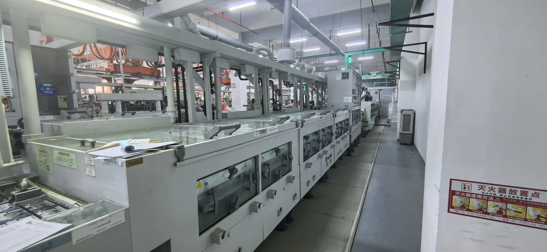


Controlled Impedance
Trace geometry and dielectric choices matched to your impedance targets.
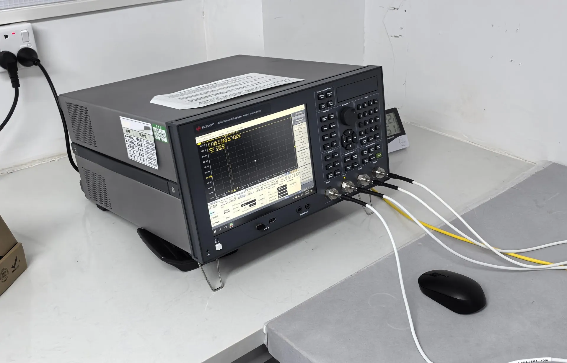
Controlled Impedance with ShinePCB
Controlled impedance keeps signals consistent across a board. We clarify targets and tolerances, propose geometry with the stack-up and agree the test method with the order.
- Impedance targets and tolerances
- Trace width and spacing
- Dielectric thickness and material
- Test coupons and method
Capability and certificates
| Positioning | Impedance Engineering | |
|---|---|---|
| Standard / prototype | Advanced / mass production | |
| Controlled Impedance | ±5% | ±7% |
Related certificates
- ISO 9001:2015133628
- UL 796E466435
- IECQ QC 080000IECQ-H NQAGB 25.0038
Source: ShinePCB capability workbook, navigation overview. Values are confirmed against your files and the assigned facility during engineering review; certificates are available on request.
Impedance tolerance by board type
| Parameter | Prototype | Mass production |
|---|---|---|
| Rigid — Impedance control tolerance | ±5% | ±7% |
| Rigid-flex — Impedance control tolerance | ±5% | ±7% |
| FPC — Impedance control tolerance | ±10% | ±5% |
| High-frequency / high-speed — Impedance tolerance | ±5% | ±8% |
| High-frequency / high-speed — Trace width tolerance | ±0.6 mil | ±1 mil |
| Factory general — impedance tolerance | ±10% | ±10% |
Source: ShinePCB capability workbook. Prototype and mass-production values are listed separately and are not interchangeable. Every value is confirmed against your files, the selected material and the assigned facility during engineering review.
Typical applications
High-speed digital interfaces
RF transmission lines
USB
Ethernet and memory buses
From prototype to production
Every order follows the same controlled sequence. Prototype and production requirements are reviewed separately.
File review
Gerber or ODB++, drill data, drawing and quantities are checked for completeness.
Engineering questions
Open points on manufacturability, materials or special processes are sent before quotation.
Stack-up and material
Construction, laminate and finish are confirmed with you and written into the order.
Fabrication
The order is released to the facility whose process and qualification fit the requirements.
Inspection and test
Inspection and electrical test follow the methods agreed for your order.
Packing and delivery
Boards are packed and shipped under the confirmed delivery terms.
What to send for a PCB review
Start with the details you have — engineering will request anything else needed for the review.
Files and details for a PCB review
- Gerber (RS-274X) or ODB++ data with drill files
- Fabrication drawing with material, thickness and finish
- Stack-up and impedance targets, if any
- Quantity for prototype and for production
- Special requirements such as IPC class, testing or packaging
Technical files stay private
Customer Gerber, BOM and design data are managed under an ISO/IEC 27001 information security system and shared only within your project.
Controlled Impedance FAQs
Can you adjust trace widths?
Engineering may propose geometry adjustments to meet your targets, and changes are confirmed with you before production.
Do you guarantee impedance?
Targets and the test method are agreed in the quotation. No performance value is assumed without project review.